Solder Fume Extractor

Posted in allmänt grinande on 2018-12-28 by Kristian

Solder fumes are evil. 

Hence, I’ve planned to add a fume extractor to my workshop for years, but haven’t been really motivated until after finishing my PhD which oddly enough resulted in time to have hobbies again -> more soldering.

PANO_20181215_160008

I used a square ventilation duct mounted on the garage wall to get the fumes out of the building, then a flexible ventilation hose from the round connector at the bottom of the duct to allow positioning of the extractor close to the work area.

The first proof of concept used a circular fan, but that suffered from low capacity as well as a tendency to roll around on the table.

Having a spare 120 mm high-capacity fan, I decided to CAD and 3D-print an adapter, which turned out really nice. It stays put where you place it and have a much higher capacity than the round one.

There will of course be a fan cover to protect the fingers, once I find it (or print a new).

(STL and FreeCAD sources are available from Thingiverse)

STM32 / ARM toolchain

Posted in nörderier with tags , on 2018-12-26 by Kristian

Since I bricked the ROTHULT lock by somehow managing to accidentally zero the firmware, I need to write my own firmware. Having done mostly embedded coding for Arduino (and AVR328P in stand-alone configuration) and ESP8266, I figured that the Arduino IDE surely had some nice additions to solve the problem.

Wrong, or at least I didn’t find any suitable for the STM32L05. (This might be wrong, there is for example Arduino IDE support for several types of STM32 processors available here )

Then what?

I decided to not go for any of the ”free for hobbyists and students” options that I got flyers for in the ST-Link package, partly because I need another IDE like I need the plague, partly because I decided to use the old macbook (hence not windows) for hacking since it has a decent command line, partly because I want to go open source for the principle of it.

As usual when I try something new, I end up trying Eclipse. Then I uninstall it. The next day, I usually reinstall it, try again, and give up once more. There are lots of rants online describing why Eclipse sucks, so it seems like I’m not alone. My main reason is that it is overly complex for the job and configuration is a hell. It is probably very nice if you have the time and energy, but it is not for me.

Anyway, if you like Eclipse, there are a few options: http://openstm32.org and https://gnu-mcu-eclipse.github.io/.

Then (after _a lot_ of searching) I found http://libopencm3.org/ which seems like the right way to do things, and I managed to blink the two LEDs on my discovery board.

What you need (assuming that you use Homebrew on your mac, similar packages are available for Linux and should be easy to find with your favorite package manager):

  • brew install arm-gcc-bin stlink open-ocd
  • git clone https://github.com/libopencm3/libopencm3-examples

Then config and run the examples.


IKEA Rothult Part 3 – Reassembly and debug connectors

Posted in allmänt grinande on 2018-12-23 by Kristian

I cut out a slot for the breakout cabling and reassembled the lock. A better solution would have been to drill a small hole in the side, desolder/resolder the wires and route them through the hole instead. I will do that _later_, if I manage to reprogram the lock.

img_20181118_180151.jpg

A quick test with various RFID cards revealed that the message on the serial bus always is ”52 46 41 4c 3a 20 63 75 72 53 74 3a 20 39 30 20 20 45 72 72 6f 72 3a 20 34 20 00 0a” which translates to ”RFAL: curSt: 90 Error: 4 ”.

This does not change regardless of the how the lock reacts to the card. Hence, useless.

It is intriguing though, why send ”error 4” even when the card is accepted?

I also connected the probe to H1 and H2, the connectors to the SWD port, but no signalling occurred on those.


Bus Pirate and Rothult

Unfortunately, the bus pirate and Rothult didn’t really work out. There is an implementation of the SWD protocol for the bus pirate, that I totally would have tried unless I had worked 50+ hour weeks for most of the winter. So I gave up and ordered some more toys from Mouser.

IMG_20181222_065051

Left to Right: STM32 discovery board, Busblaster v4, ST-Link V2.1 with cables

OK, the STM32 discovery board would have been sufficient, it has a built in separately usable ST-Link, but the other items more or less paid for themselves due to the free delivery over 50 dollars thing. Or at least that is what I tell myself…

Waiting for Fedex

Have you ever tried getting a delivery with Fedex in a rural area? Then you know.

To be continued in part 4, ”connecting and using the debug tools”

Meanwhile, install OpenOCD, gdb, and if running an appropriate OS, the ST-Link utility.

IKEA ROTHULT, Part 2 – Connecting wires to the header

Posted in allmänt grinande on 2018-11-18 by Kristian

Having disassembled the lock and gained some kind of feeling for what is on the PCB, it is time to see if we can do something to it.

We could of course hot air the processor and solder something else in place instead (as done here with another IKEA product) but that is not as fun as it is to reprogram the device to do something else. So let’s attempt reprogramming!

Connecting a debugger

Step one is to carefully solder six wires to the small header to be able to connect instruments to the board. Later, I also added (not shown in the first photo) a ground wire directly to the battery compartment header to be able to connect the oscilloscope ground easier. Then I soldered an ordinary pin connector, left-over from an Arduino nano kit, to the wires, which makes oscilloscope connection easier.

The wires are somewhat difficult to solder to the PCB, and be careful to not melt the plastic.

IMG_20181117_174204.jpg


The idea is to use the wires to connect to openocd through a bus pirate board, to hopefully be able to dump the IKEA firmware, and analyze it. If you need to flash the BP, the ds30 loader can be found here, the link in the howto is broken.

In part one we identified the pin-out of the debug header, from left to right in the picture:

  • H1 – Pin 24 (PA14, SWCLK, USART2_TX)
  • H2 – Pin 23 (PA13, SWDIO)
  • H3 – Pin 17 (VDD, 3V – see below)
  • H4 – PCB ground plane (if one look at the battery compartment, the negative pole of is connected to the same PCB plane and this is also confirmed by a circuit beep tester)
  • H5 – Pin 20 (PA10, USART1_RX)
  • H6 – Pin 19 (PA9, MCO, USART1_TX)

rothult10

We will examine those pins in turn with a volt meter and an oscilloscope before the bus pirate is connected.

Power pins

We need to examine VDD closer to avoid releasing the magic smoke. The data sheet for the CPU specifies 1.65 V to 3.6 V power supply, but it could be anywhere in that range. The RFID circuit wants 2.4V to 5.5V, but is flexible down to 1.65V on its data pins. (The data sheets are linked in the previous post).

Looking at the PCB photos, it seems as if we can read the print on what seems to be a regulator circuit, so let’s check that as well.

A quick look through a magnifying glass reveals that most likely indeed is a regulator, an 6210A in a SOT-89-5 package, and from the other markings, I guessed that the output voltage is 3.0 volts. I haven’t been able to identify the manufacturer, unfortunately.

I took the opportunity to measure on the pins at the same time, which confirmed both the connectivity as in the list above, and revealed that the VDD indeed is at or slightly below 3 volts.

dsc_62821 (1)

Untitled

Data Pins

Having investigated the power pins, we turn towards the data pins.

I’m actually primarily interested in H1 and H2, since they are connected to the serial wire debug feature (SWCLK, SWDIO) (link to relevant datasheet) which potentially is useful as an attack vector. (And hopefully https://github.com/disk91/PySWD/ can be used for something nice), but figuring out if anything is sent on the other UART is also highly relevant.

So let’s start with USART1 and do the SWD investigations in the next post.

Oscilloscope on H6 – Pin 19 (PA9, MCO, USART1_TX)

Touching one of the IKEA smart cards to the device results in a pulse train on this pin, as shown below. Interesting!

Unfortunately, we get the same message (52 46 41 4C 3A 20 <-> ”RFAL:  ”) regardless of if it is the IKEA card, or an SL card. Something is better than nothing, however, and this is without the motor etc installed so it could be a partial message.

(RFAL  is a reasonable part of a message.)

H6

Oscilloscope image of H6

To be continued…


Teardown of the IKEA ROTHULT RFID lock

Posted in in English, nörderier on 2018-11-01 by Kristian

EDIT: You can connect an stlink to the debug header. I never got that far in the writeup though, due to this being the first ARM project I looked at combined with the vacation ending. I have however tested it and it works.

Disclaimer: If you believe any of the below and burn down your house, lose your dog, or break your lock, or something else that is good or bad happens, it is your own fault. The likelihood of something being wrong is close to 100%.

The IKEA ROTHULT is an RFID-enabled motorized lock for desks, cupboards, etc.

Obviously, it would be nice if it could be connected to, for example, a mysensors network and used for home automation.

Teardown

The ROTHULT is kept together by four screws, no tricky plastic tabs. Simply unscrew the battery compartment and the lid, then lift it away.

Inside, you find the bolt, a gearbox arrangement with a small motor, and a circuit board. The RFID antenna is beneath a snap-in lid (visible in the first picture) and connected through four pins to the PCB. Two microswitches are used as end stops for the bolt.

rothult3

Unfortunately, the RFID antenna is soldered to the main PCB, which means that it cannot be lifted out of the box easily. Everything else can be removed without violence.


To remove the lid over the RFID antenna, lift CAREFULLY at the slots, while pushing the plastic tabs from the inside.

rothult6

If you don’t manage to push ”good enough” on the tabs, they are likely to break. (The two closest to the PCB on mine did, but it doesn’t really matter, if you are to use the lock as a lock later, it will not be visible and super glue is cheap :-) )

Lifting the lid reveals a PCB with an antenna on it. Unfortunately, that is all it seems to be, there is no hidden I2C/SPI/serial RFID module ready to be harvested.

PCB

Let’s take a closer look at the PCB.

DSC_6282

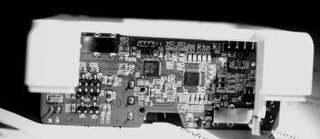
Q3-Q8 on top to the right seems to be the power transistors driving the motor.

The build is primarily surface-mounted (no surprise), and uses two main integrated circuits – a guess is that the right one handle the RFID decoding, and the left is the main processor (if there is such a thing in this device). Then, if we are lucky, the header right above the integrated circuit could be a programming/debug header.

Processor

rothult10

A closer look on the suspected CPU reveals the ST logo, and an identification number: L051K86, which is a reasonable match to the STM32L051K8 processor with LQFP32 pinout (datasheet).

If this indeed is the case, the pinout from the datasheet is shown below, rotated to match the photo above.

rothult11-e1541064985721.png

Looking at the header (ref black-and-white photo), from left (H1) to right (H6), the header pins appear to be connected as below – please note, this is still to be confirmed by a second view as well as with measurements!

  • H1 – Pin 24 (PA14, SWCLK, USART2_TX)
  • H2 – Pin 23 (PA13, SWDIO)
  • H3 – Pin 17 (VDD)
  • H4 – PCB ground plane (if one look at the battery compartment, the negative pole of is connected to the same PCB plane)
  • H5 – Pin 20 (PA10, USART1_RX)
  • H6 – Pin 19 (PA9, MCO, USART1_TX)

According to the datasheet (section 3.9 boot modes), programming the flash memory is done by using SPI1 (PA4-PA7), SPI2 (PB12-PB15), USART1 (PA9, PA10), or USART2 (PA2, PA3).

Since we indeed have USART1 connected to H5-H6 is would seem as if we can access the flash through this header (if the BOOT0 pin can be manipulated / is connected in an appropriate way). The datasheet in turn refers to STM32 memory boot mode AN2606. That datasheet can be found here.

For the remaining pins, H1/H2 are connected to the serial wire debug feature (SWCLK, SWDIO), see for example this datasheet for more details.

Let’s leave it at this for now, and move on to the rest of the circuitry.

RFID Decoder

The initial assumption is that integrated circuit #2 is a dedicated RFID decoder.

rothult12

This is confirmed by a new macro photo (the print on this circuit is really hard to read) which identifies it as an AS3911 (datasheet) NFC Initiator / HF reader IC.

The ams logo is quite identifiable once you know it is supposed to be there.

Looking in the datasheet, we find the pinout:

rothult13.png

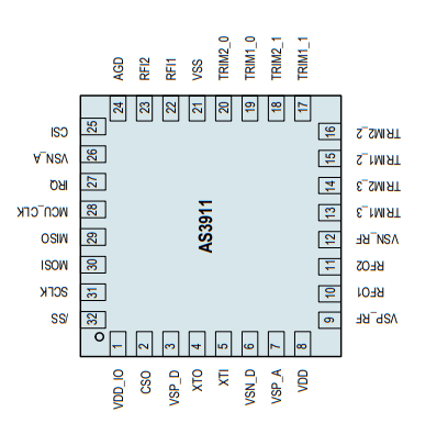
Again, his is oriented the same direction as in the overview PCB photo (but not as in the closeup showing the markings) and the connections to the CPU can be traced:

  • AS3911 Pin 32 (/SS) <-> CPU Pin 10 (SPI1_NSS)
  • AS3911 Pin 31 (SCLK) <-> CPU Pin 11 (SPI1_SCLK)
  • AS3911 Pin 30 (MOSI) <-> CPU Pin 13 (SPI1_MOSI)
  • AS3911 Pin 29 (MISO) <-> CPU Pin 12 (SPI1_MISO)
  • AS3911 Pin 27 (IRQ) <-> CPU Pin 14 (PB0)

Hence, the AS3911 is connected to the CPU through SPI.

End Switches

The two microswitches seems to switch VDD/GND to an IO pin depending on their position.

  • Switch 1 (above the summer) is connected to CPU pin 27 (PB4)
  • Switch 2 (not above the summer :-)) is connected to CPU pin 28 (PB5)

Summer

No idea.

Motor Drivers

Not investigated yet.

Continued in part 2, where we wire up the debug header and decode the serial output.


Mysensors-capable CO2-sensor

Posted in nörderier with tags on 2018-10-16 by Kristian

I have suspected for a while that the CO2 levels at night in my bedroom are quite high, and when there was a sale on Senseair S8 sensors a few weeks ago, I decided to get one.

The original intent was to use the ESPEasy-based controller I use to control the air conditioning, but the NodeMCU board runs on 3.3V and the Senseair S8 wants 5V so it was easier to do something based on my go-to solution for remote sensors, mysensors.org.

A quick breadboard-build confirmed that yes, CO2 indeed gets high during the night (the Y axis is PPM, and it falls well within the uncomfortable levels).

To mount the sensor in the room, I needed a well-vented enclosure, and since the sensor is anything but cheap, it had to be reasonably sturdy as well.

Hence, FreeCAD and 3D-printing!

The enclosure is made from three parts and kept together with hot glue. A vented dome encloses the sensor which is mounted on a plate. Glue the cables to the plate to avoid the sensor bouncing around. All files are available at thingiverse. 

Code

To get this working,  combine the code example from https://www.co2meter.com/blogs/news/35432257-arduino-code-for-k-30-co2-sensor-works-for-s8-sensor-too with the code example from https://forum.mysensors.org/topic/6528/mh-z19-co2-sensor/7 to enable CO2 level reporting to homeassistant.

Since the licensing for the first example from co2meter.com is unclear, I leave it as an exercise to the reader to combine the two (Hint: Use sendRequest() and getValue() + all related code from co2meter.com to read the CO2 PPM, then use the mysensors example to pass it on to the controller)

Then what?

The sensor readings will be used to control two fans connected to a normal Z-Wave relay (or similar) that will push in fresh air through the vents when the CO2 levels are too high.

mysensors-capable bbq thermometer

Posted in nörderier with tags , , , , on 2018-08-10 by Kristian

Let’s build a wireless meat thermometer!

There is of course already a wide range of wireless thermometers available,  but what is the fun in that? Also, they are quite expensive and there is (in general) no way to use the data cleverly, the presentation is limited to an app or a dedicate thermometer control box. Another option could be to build for example a WLANThermo or a HeatMeter.

Bill of materials:

  • Arduino nano – I have a bunch. The power-conscious person will use something else, I intend to power this off an old powerbank
  • Probe – see below
  • 47k resistor
  • various cables, solder, solder iron
  • NRF24L01 Radio for the mysensors functionality


We start with acquiring a probe. Unless you shop from Ali Express and is prepared to wait for a few weeks (and also these days if you are in Sweden, pay the lovely processing fees from Postnord), it is likely that the IKEA FANTAST timer/thermometer (SWE link) (US link) is the cheapest choice. It seems to have a 220k @ 25C NTC probe.

Start by disassembling the FANTAST and scavenge the 2.5 mm jack socket. The FANTAST can be reassembled and used as a timer without the probe and socket. The box is held together by four small screws. Carefully unscrew them, lift the lid, and desolder the socket.

Then we will connect the FANTAST probe in line with a bias resistor. I somewhat arbitrarily choose a 47k ohm resistor. The resistor is soldered to the socket pin which is connected to the metal casing of the probe, the probe is not isolated.

Make a connection from the Arduino’s 5V pin to VDD on the voltage divider, from A0 to the middle of the voltage divider, and from GND to the bottom of the voltage divider. This allows us to eliminate the supply voltage from the calculations.


Now we can do some testing – let’s code a simple to-the-serial-port thermometer!

We start by measuring the resistance of the probe – this code is based on the Arduino Analoginput demo. Change the ”loop” function to the below and upload it:

void loop() {
  int sv=0;
  
  for(int i=0;i<10;i++) {
    
  // read the value from the sensor:
  
  sensorValue = analogRead(sensorPin);
  sv=sv+sensorValue;
  delay(10);
  }

  sensorValue=sv/10;
  // turn the ledPin on
  digitalWrite(ledPin, HIGH);
  // stop the program for <sensorValue> milliseconds:
  Serial.print("Volts: ");
  Serial.println(sensorValue*5.0/1024.0);
  Serial.print("Ohms: ");

  // vout = (vdd * r2 )/(r1+r2)
  // (r1+r2)*vout = vdd * r2
  // r1*vout = vdd*r2-vout*r2
  // r1 = (vdd-vout)*r2/vout
  // now add the equation for the resistance and eliminate vdd


  Serial.println((1.0-sensorValue/1024.0)*47000/(sensorValue/1024.0)); // this is our probe resistance.

  Serial.println("---");
  
  delay(sensorValue);
  // turn the ledPin off:
  digitalWrite(ledPin, LOW);
  // stop the program for for <sensorValue> milliseconds:
  delay(sensorValue);
}

If everything works, the serial port should print resistance values. They will likely jump up and down a bit, but averaging over 10 samples helps a bit. This we will use to calculate the Steinhart-Hart coefficients. Simply place the probe in three different water baths with different temperature, measure the resistance with the sketch, and measure the temperature with a decent thermometer. Then use this calculator to get a,b,c. I got the following using my Thermapen as the ”gold standard”:


                • 26.3 C (79.34 F)-> 220378 ohm


        • 74.5 C (166.1 F) -> 31384 ohm


        • 50.8 C (123.44 F) -> 76722 ohm


  The resulting values are a=0.0005887972095510851, b=0.00021455581402332063, c=5.958141261835043e-8 which seems to be good enough when checking a few more random points in my cup of tea. So let’s modify the arduino code to calculate the temperature as well:

int sensorPin = A0; // select the input pin for the potentiometer
int ledPin = 13; // select the pin for the LED
int sensorValue; // variable to store the value coming from the sensor

// steinhart-hart constants for my probe.
double a=0.0005887972095510851, b=0.00021455581402332063, c=5.958141261835043e-8;

void setup() {
// declare the ledPin as an OUTPUT:
pinMode(ledPin, OUTPUT);
Serial.begin(9600);
}

void loop() {
int sv=0;
double res, lt, temp;

for(int i=0;i<10;i++) {

// read the value from the sensor:

sensorValue = analogRead(sensorPin);
sv=sv+sensorValue;
delay(10);
}

sensorValue=sv/10;
// turn the ledPin on
digitalWrite(ledPin, HIGH);
// stop the program for <sensorValue> milliseconds:
Serial.print("Volts: ");
Serial.println(sensorValue*5.0/1024.0);
Serial.print("Ohms: ");

// vout = (vdd * r2 )/(r1+r2)
// (r1+r2)*vout = vdd * r2
// r1*vout = vdd*r2-vout*r2
// r1 = (vdd-vout)*r2/vout
// now add the equation for the resistance and eliminate vdd


res = ((1.0-sensorValue/1024.0)*47000/(sensorValue/1024.0)); // this is our probe resistance.
Serial.println(res);
Serial.println("---");

// calculate the actual temperature

lt = log(res);
temp = 1 / (a+b*lt+c*lt*lt*lt); // in kelvin
Serial.print("Kelvin: ");
Serial.println(temp);
Serial.print("Celsius: ");
Serial.println(temp-273.15);

delay(sensorValue);
// turn the ledPin off:
digitalWrite(ledPin, LOW);
// stop the program for for <sensorValue> milliseconds:
delay(sensorValue);
}

This seems to work fine, at least the resulting temperature measurements are in line with my Thermapen. The remaining work is to connect the radio, turn the above into a mysensors sketch, and create a nice automation to handle the data.

The final mysensors sketch is available on github, the automation has not been implemented yet.

IMG_20180812_151027

mysensorsbbqhass


Air conditioning remote controller codes for Duracraft AMD 8500 E

Posted in nörderier on 2018-07-01 by Kristian

For air conditioning units using this type of remote:

xsdfsdfsdf

All codes use the NEC protocol and are 32 bit. Seems to work with the espeasy IR remote TX.

ON/OFF – 8F758A7

UP – 8F750AF

DOWN – 8F720DF

C/F – 8F700FF

MODE – 8F77887

SPEED – 8F7906F

TIMER – 8F7807F


Vattennivåvakt till IKEA VÄXER

Posted in nörderier, växtodling on 2018-05-06 by Kristian

Vi har en hoper ”IKEA VÄXER”. Det fungerar tokbra, om man bara kommer ihåg att vattna dem. Det gör vi inte, så vi får massor av torr sallat.

Alltså behövs en nivåvakt till vattnet. Den mycket modige hade såklart satt en automatisk påfyllare, men eftersom vi har dem inomhus på andra våningen i ett trähus så är vi inte så modiga.

Insats med nivåbrytare

Jag hade ett par nivåbrytare (länk till kjell, leta efter ”float switch” om du hellre handlar på aliexpress) över efter ett experiment förra året som verkade kunna vara perfekta att kontrollera vätskenivån med utan att behöva meckla med konduktivitet och annat besvärligt.

För att få fast den i växtlådan så caddade jag en hållare och 3D-printade den. Filerna finns på thingiverse (https://www.thingiverse.com/thing:2896162) inklusive freecadfilen om någon vill rita en med lite annan höjd på fästet. (Den mycket händige kan säkert peta ihop något som går att köra customizer på, men det är överkurs för min del…).

Brytaren slår till någonstans mellan 1-2 av mina vattenkannor i odlingslådan, så det finns fortfarande vatten kvar när den larmar.

Mysensorsnod

För att få signalen från nivåbrytaren till mig (dvs, in i Homeassistant) så kopplade jag på en mysensorsnod med strömbrytarfunktion (https://www.mysensors.org/build/binary).

Observera att Homeassistant kommer att ignorera noden om exempelkoden från sidan används, man behöver sätta ett namn på nodtypen i ”presentation”-funktionen.

Ändra den till tex

void presentation() {
  sendSketchInfo("Water Sensor", "1.0");
  present(CHILD_ID, S_DOOR); 
}

så fungerar det sedan.

Koppla in nivåbrytaren enligt exemplet på mysensorssidan och testa att det fungerar genom att lyfta flottören upp och ner och se värdet ändras i Homeassistant.

Konfiguration i Homeassistant

Mysensorsmodulen i Homeassistant kommer att presentera noden som en binärsensor med värdena ”on” och ”off”. Jag ville ha in den som en fuktighetssensor i Homeassistants växtmodul, och skrev därför en templatesensor som kan ha värdena 0 samt 100.

- platform: template
  sensors:
     vattenlarm_ikea:
         unit_of_measurement: '%'
         value_template: '{% if is_state("binary_sensor.water_sensor_8_1","on") %} 100 {% else %} 0 {% endif %}'

binary_sensor.water_sensor_8_1 är namnet som Homeassistant satte på nivåbrytaren när den kopplade upp sig. Byts givetvis ut mot vad som passar.

(På sista raden står det value_template: ‘{% if is_state(”binary_sensor.water_sensor_8_1″,”on”) %} 100 {% else %} 0 {% endif %}’)

Sista steget var att lägga till en komponent med Homeassistants växtmodul och kombinera 433 MHz-termometern med nivåsensorn (som nu är en fuktsensor):

ikeaodling:
  sensors:
    moisture: sensor.vattenlarm_ikea
    temperature: sensor.biblioteket_temperature
  min_moisture: 99

”Ikeaodling” kommer då att hamna i state ”problem” när nivåbrytaren larmar, och det kan man fortsätta automatisera på, ex skicka textmeddelande till telefonen.


Lussehundar

Posted in allmänt grinande on 2017-11-26 by Kristian
  • 850 gram vetemjöl
  • 200 gram smör
  • 5 dl mjölk
  • 50 gram kakaopulver
  • 1 tsk salt
  • 2.5 dl strösocker
  • 50 g färsk jäst eller 14 g torrjäst

Bakas som lussekatter, för det är lussekatter fast med kakao istället för saffran.